
In the previous post I found some interesting relation between the linear alignments of piers in Nave plus Choir and the circular alignments in Apse and Ambulatory. See Figure 9 in the previous post. In this post I will carry on with the analysis of the Floor Plan.
THE NAVE-AISLES’ WALLS AND THEIR RELATION WITH THE AMBULATORY’S ROUND COLUMNS.
In the Floor Plan I have drawn new, straight lines along the walls of the Nave’s North and South Aisles and through the Transept- and the Choir piers. Then I added another circle with the High Altar Point as centre that ‘touches’ these straight lines tangentially. This circle traverses the Ambulatory space to the round Ambulatory columns. This circle however, doe snot run through the column’s centers, as you can see in the next Figure 10 (click on the image to enlarge):

Fig. 10 Alignments of Nave-Aisles with the Chevet’s Ambulatory circle. Including measurement numbers for Nave , Aisle width and Buttress ‘length’ (Fibonacci ) numbers
Fig. 10 Alignments of Nave-Aisles with the Chevet’s Ambulatory Circle, Including measurement Numbers for the Nave,Aisles and Buttresses ‘length’ (Fibonacci) Numbers.
In the above Fig. 10 you can notice clearly that the added circle runs close to the round Ambulatory columns but not through their centers! Jean Villettte has pointed out too that the main circles in the Chevet are offset from the High Altar Point (HAP), yet different from the Apse’s Boss points. I will come back to this observation later.
The new lines along the walls of the Nave-Aisles (compare Fig. 9. and Fig.10.) run parallel to the Nave’s central axis at a distance of 42 mm as I measured on the J.V. ‘s Floor Plan. Another Fibonacci number turned up as follows. I found the Apse radius to be equal to 21 mm, and the Aisle walls at 42 mm from the Nave’s axis and the outer side of the Nave buttresses at 55 mm, therefore the Nave buttresses extend 13 mm from the Aisle walls!
THE TRANSEPT’S ARCADE PIERS AND THE THREE MAJOR CHAPELS’ CENTRE POINTS.
The same procedure described above can be repeated for the –two- Transept’s Arcade piers. The blue lines drawn from the West through the Transept Arcade piers towards the East join with a circle through the major Chapel’s centre points. In the next Figure 11 this circle has been shown in blue color for visual clarity. (click to enlarge the image):
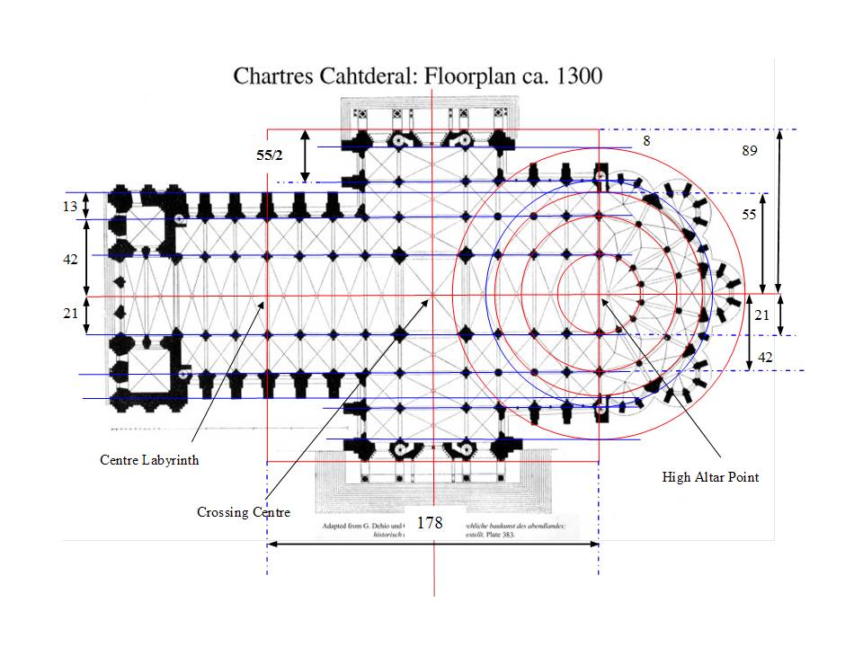
Fig.11. Chartres Floor Plan showing all linear and Circular alignments plus measurements.
Fig.11. Chartres Floor Plan showing all linear and Circular alignments plus measurements.
The red line forming the Northern, horizontal side of the ‘Grand Square’ that runs along the outer edge of the North Portal (door) buttresses , I measured at a distance of 55/2 mm from the blue line running through the Transept’s Arcade piers. See Fig. 11
I want for a moment to go back to the thoughts and musings about the buttresses fortifying the Nave (isles) walls described in the previous post. This finding of Fibonacci number 13 for the length of the buttresses extending outwards from the inner Nave walls, adds, in my opinion, another argument in support of the possible conclusion that it is no coincidence that the lines along the outer ‘ends’ of these Nave buttresses join with the -other- Ambulatory circle. Perhaps this was a deliberate design decision! And this gets even stronger when we add another argument to it. In the analysis of the Transept and its position and size in relation to the whole plan, we will see, later in this post, that the same sizing, the same number 13, shows up for the east side Transept buttresses!!!
THE TRANSEPT, ITS POSITION AND SIZE IN THE FLOOR PLAN.
Let me first address the terminology I am using. The Cathedral is laid out in the form of a Latin Cross. The transverse ‘beam’, of the Latin Cross is oriented perpendicular to the main, long, central axis. This transverse ‘beam’ consists of Transept plus on either side its Aisles. The Transept runs along its North – South axis and meets the Nave forming the Crossing. The Northern and Southern part of the Aisles – the ‘arms’ are bounded on the outside by walls and buttresses. On the Northern side the Aisles and Transept are ended by the three-door North Portal. On the Southern end a similar Portal is found.
To be able to analyze the Transept and its Aisles I went back to an earlier Figure ( Fig.7.) that does not show all the blue lines in the Nave and Aisles so as to have a more ‘clean slate’ to draw on possible alignments in the Transept. In addition I have re-drawn Fig. 7. to improve upon the precision of the lines and circles drawn on it, in particular the Ambulatory buttresses inner wall circle.
After having found that the Golden Section played a role in the division of the vertical line at the East side of the ‘Grand Square’ , I wondered if applying a Golden Section cut to the horizontal sides would yield any significant alignments in the Transept. So, I next applied the Golden Section to each half of the horizontal top side of the Grand Square, each half being 89 mm long. It resulted in two unequal line sections of 34 and 55 mm long. This division was done not by geometric construction but by ‘metrics’, by calculation and measuring out these distances. But if you apply the Golden Section in this manner still you have to make another decision. Why? When dividing according to the Golden Section, there are two ways to do that: either the ‘short’ line section lies toward the outer corner of the ‘Grand Square’ and the ‘long’ end towards the central axis of the Grand Square or vice versa. I chose the short line section of 34 mm to lie against the central, vertical axis of the ‘Grand Square’. At these Golden Section cut points I have drawn vertical blue lines. In the next Fig. 12. I have shown these lines so their position can be compared to the position of the walls of the Transept’s arms. (click to enlarge ):

Fig.12. Comparison of the positions of the Transept walls with the blue lines at the Golden Section cut points of the North and South sides of the Grand Square.
Fig.12. Comparison of the positions of the Transept walls with the blue lines at the Golden Section cut points of the North and South sides of the Grand Square.
You can clearly notice that these blue, ‘phi’ lines do not coincide with either of the Transept Aisle walls. Neither do they run through the centre points of the piers of the Nave. The blue ‘phi’ line on the West side is even further removed from the actual wall than the one on the East side. It looks to me like another method was used by the architect/master builder to arrive at the position of the actual Transept walls. Ignoring for the moment the obvious other North-South straight line alignments I can draw, namely those through the major crossing piers, let’s try to draw straight lines along the outside of the Transept buttresses, in analogy with what we have seen for the Nave buttresses. This is done in the next Figure 13. (click on the image to enlarge):
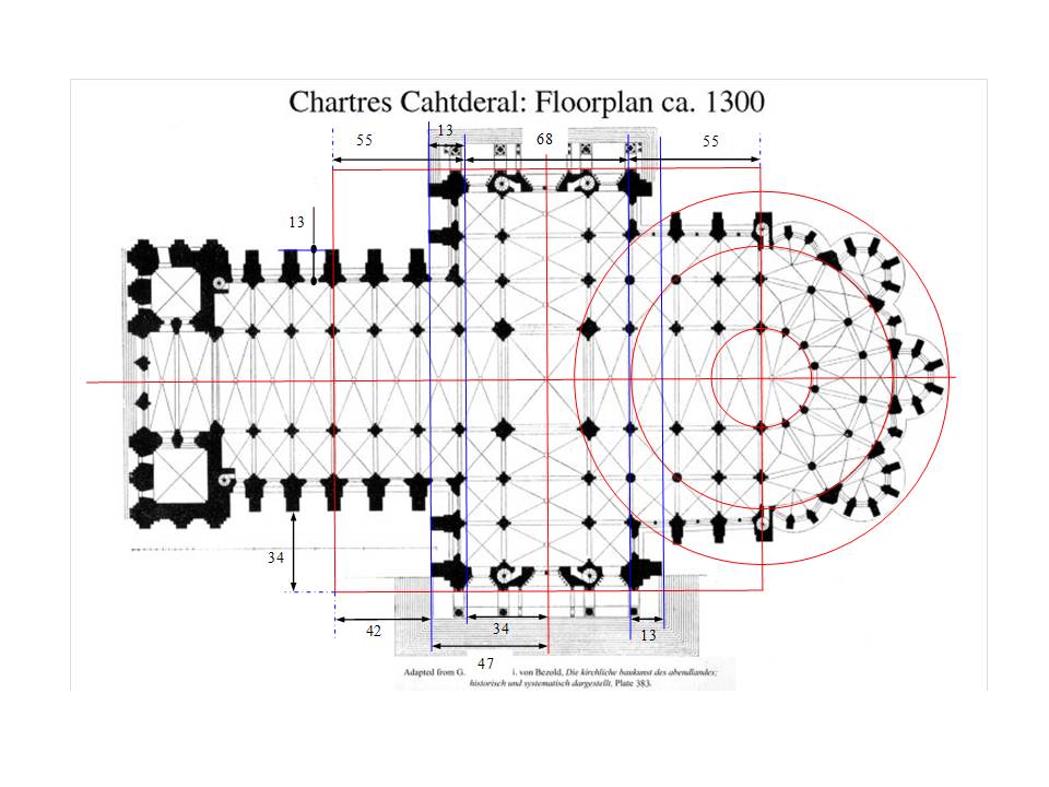
Fig. 13. The Transept Aisles’ Buttresses’ outer alignments.
Fig. 13. The Transept Aisles’ Buttresses’ outer alignments.
We can see in Fig.13 that the Transept buttresses on the West side (left) ,both on the North and South arm align well. On the East side the alignment is less strong in particular for the North East buttress which is clearly shorter. The closeness of the adjacent Vestry building may have necessitated the shortening of this North East buttress. The Vestry is not shown on this Floor plan. Measuring the position of these new lines shows they are 13 mm from the ‘phi’ lines. I have also shown in Fig. 13. the previously determined measurements for outer edge of the Nave buttresses that are also equal to 13 mm. Thus again Fibonacci number 13 is showing up. Now you may say that the Transept’s buttresses’ number refers to a line that indeed lies at a Golden Section cut point, but it has no material counterpart ! That brings us back to the question of the positions of the actual walls and total width of the Transept plus Aisles. What measure, what method or what geometry was used to arrive at these?
THE WIDTH OF THE TRANSEPT AND ITS DIVISIONS, AD QUADRATUM ?
In trying to answer that question let us look at the blue, Golden Section lines again. If the architect/master builder would have chosen these as final positions of the Transept walls and next would have to divide the total Transept width into three parts, (two aisles and the –midway- transept), he would have arrived at pier positions whose distances would be out of step with those along the Nave. They would have been shorter than those in the Nave and Choir. The rhythm of bay openings and piers, would have been disturbed. The position of the Transept walls, and its subsequent divisions ,I believe, should mesh in with the Nave arcade bay widths, and those of the Choir arcade bays to create a harmonious, unified rhythm of the piers and openings. The question thus is how was position of the walls of the Transept been chosen? Apparently not with the help of a Golden Section division! But then how ? The Grand Square can be thought of to consist of four smaller squares. Perhaps an Ad Quadratum type of construction using the diagonal of the smaller square (89 by 89) was used to arrive at the position of the Transept walls? Let us test this out. In the following Fig. 14 I have drawn the diagonal from the High Altar Point to the opposite corner of the upper, right hand, smaller square and next circled its length around Westward onto the Nave axis to define a point in which to erect a line perpendicular to the Nave axis. The same procedure is repeated at the Labyrinth Centre Point, resulting in a line perpendicular to the Nave axis at the East side of the Transept. These newest lines I have shown in a green color in the next figure. (click on image to enlarge):

Fig. 14. The Ad Quadratum construction of a possible Transept wall position (shown as green line).
Fig. 14. The Ad Quadratum construction of a possible Transept wall position (shown as green line).
At first glance the green lines look like a better fit to marking the position of the actual Transept walls. However, on close inspection it can be seen in Fig. 14 that these lines do not run through the centers of the piers on the Nave side as well as those on the Choir side! From which I conclude that an Ad Quadratum – diagonal type construction has not been used to arrive at the Transept’s width. This conclusion is further supported by the fact that in the placement of the piers in Nave and Choir and Crossing we can clearly see a rectangular pattern rather than a square pattern.
CHARTRES’ CATHEDRAL’S RECTANGULAR CROSSING.
As I have already said in an earlier post, the rectangular crossing in Chartres Cathedral is one of its remarkable features. All major Gothic cathedrals built in West Europe, like for instance Amiens, Cologne have a square crossing of Nave and Transept. When we look at their floor plans and see their square patterns, it is not difficult to understand why one comes to conclude that the Ad Quadratum method is the key to the lay out of the plan. Also from a practical point of view, it is true that setting out a plan on the ground using squares is easier. The rectangular crossing presents a difficulty in explaining how this figure was arrived at by the architect/builder. For, when the plan is in the form of a Latin Cross, it is only a small step – in the mind- to assume that the square at the crossing is the starting point for the design as well as for the construction. With Chartres’ rectangular formed Crossing, however that assumption is challenged ! A rectangle is not a regular, circle symmetric figure, like the square, the hexagon, the octagon and so on. It is not a figure that one intuitively would take as the geometric figure that ‘sets the pattern’. Hence, in literature[1] I find that various other regular geometric figures have been hypothesized to be the starting point at the Crossing for developing the remainder of the plan. The rectangle in such explanation then is a subset of the regular hexagon or pentagon chosen to be the primary source for generating the pattern.
THE APSE RATHER THAN THE CROSSING AS MOST CENTRAL AREA
However, still the question remained in my mind why keep focusing on the Crossing and its geometric figure? Yes, the Crossing jumps out at you looking at a cathedral’s plan shaped in the form of a Latin Cross. It lies at the heart of the Transept and Nave plus Choir. It indeed is at the heart of the physical structure, the material edifice. However, the Crossing and its center is not the most significant and meaningful point in the cathedral, seen from a spiritual and liturgical angle. The most meaningful and highly symbolical point, charged as it were with intense sacred energy, I would say is the High Altar Point that lies at end of the Choir. Around that Point lies the consecrated area and space of the Apse. Around the Sanctuary of the Apse one find the semi-circular Ambulatory and its radial Chapels all centered onto the same High Altar Point.
After this realization of the significance of the High Altar Point, I could more easily let go of the idea of the Crossing’s centre point and its naturally dominating position as the ultimate start point of the design of the floor plan and start looking into a possible pattern in the spacing of the Nave bays.
THE NAVE BAYS’ OPENINGS, SPACING OF PIERS, AD TRIANGULUM.
The basic pattern of placement of the Nave piers is amplified in the large rectangle of the Crossing. Why was a shorter distance in West to East direction chosen for the Nave piers than in the North-South direction? Before trying to answer that question let us consider the background, the situation and context in which the design and construction took place. The cathedral needed to be rebuilt after a devastating fire that left the west side and towers standing. It was a re-construction not a ‘green field site’ construction. The architect/builder had to work within the constraints imposed and the opportunities provided by the situation. Two factors in my mind stand out, first the vast crypt that was left untouched by the fire provided a solid foundation for the new cathedral –saving time and resources and second the Holy fire and zeal that arose among the people to raise a new, glorious and grander cathedral dedicated to Mary after the Veil of the Virgin Mary , the Sancta Camisia, that sacred relic, was miraculously recovered undamaged by the fire.
My answer to the question of how the size of the Nave bay openings was determined is as follows. If the goal was a grander and greater new Cathedral then maximum use had to be made of the vast, existing crypt as the foundation, then maximizing the width of the Nave plus Aisles would be the logical consequence. We know now in this day and age that indeed Chartres has the widest Nave ( 16.4 meters) of all Gothic Cathedrals in Western Europe. But, with boldly aiming for the widest Nave comes the need for ensuring the stability of the overarching vaults (North–South direction) and the stability of the Nave arcade (in West-East direction). One design strategy is (and has always been) to use over-design, thus the buttresses of the Nave are made massive and are fitted with three flying buttresses all the way high up to stabilize the Nave ‘s wide arching vaults. To stabilize the Nave arcade is another matter. One factor to help would obviously be the size of the piers, to make them sturdy and of wide diameter. Another factor to help the stabilization is to not over-extend the distance between Nave bay piers, to not over-size the Nave bay openings. The shorter the bay openings, the closer the Nave piers are together, the lesser they ‘lean’ on each other to share the load of their arches. A square pattern has not been implemented in Chartres as we have seen. What about a triangular pattern? .An Ad Triangulum pattern ( with apex pointing Eastward) governing the placement of the Nave piers would bring these piers closer together ( in West-East direction) than a square pattern would and hence would provide more stability to the Nave arcade. I did a detailed analysis of the Nave bay lengths measurements and the scale of the J.V. Floor Plan and confirmed that the Nave and Choir piers are positioned according to an Ad Triangulum pattern using equilateral triangles. In the coming posts I will present these details.
It is interesting to note that the above thoughts and considerations about a square versus triangular placement patterns amounts to the crux of the debate held in the 14th century during he design and construction of the Milan cathedral. A debate on how to proceed construction of the cathedrals’ elevation. This discussion has been well documented and still exists today in the Milan archives.
The result of the detailed analysis is that we can conclude that the piers of the Nave are designed to be placed at equidistant points along the main axis of Nave between the Labyrinth point and the High Altar Point. In other words along the Nave’s axis but within the ‘Grand Square’ .From the point of leaving the Narthex between the two towers and entering the Nave going to the High Altar Point, there are twelve bays, counting the double sized Crossing as one. There are three bays between Narthex and Labyrinth Centre and nine bays within the Grand Square. Thus the Grand Square contains ten equal sized bay openings.The average bay thus is 178 mm / 10 which is equal to 17.8 mm. The Crossing spans 2 times 17.8 or 35.6 mm. At this point we can do a ‘ reality check’ with this scaled down measure of 35.6 mm . If we assume the scale of Jean Villettte’s Floor Plan to be 1: 393 this measurement scale up to an actual distance of 35.6 * 393 = 13991 mm. The distance of the Crossing Piers on the South side ( West to East) has been reported (Villette, Lassus , and others) as being 13.99 meters !
In the next Figure 15 I have indicated the position of the Nave piers that align with the actual Transept’s walls by dashed lines. Note that these dashed lines fall in between the blue, ‘phi’ lines and the green lines.

Figure 15. The actual alignment of the Transept walls with the corresponding Nave piers shown by the dashed lines and compared to the ‘phi’ lines and V2 lines.
Figure 15. The actual alignment of the Transept walls with the corresponding Nave piers shown by the dashed lines and compared to the ‘phi’ lines and V2 lines.
Thus we can say the Transept walls are placed in sync with the Nave Piers that have been designed to be placed in an Ad Triangulum pattern !
[1] Von Simson , James , Padovan
